
In practice, clamp force is determined by multiplying the part’s projected area by the actual peak cavity pressure, then applying a safety margin to account for gating, venting, and dynamic effects. Shot size is determined by calculating the part volume based on the CAD geometry, converting that volume to mass using the polymer density, adding the runner and main gate volumes or accounting for hot runner savings, and then selecting an injection unit with ample reserve capacity to provide cushioning and process stability. For large machines, scale amplifies all differences—heavier molds, longer runners, and multi-cavity layouts require higher pressures and larger shot sizes.
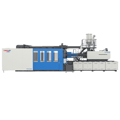
Large Injection Molding Machine: The Impact of Projected Area, Cavity Pressure, and Material on Clamping Requirements
Accurately determining clamp force for a large injection molding machine begins with understanding the true meaning of projected area and how cavity pressure interacts with material rheology and mold design. The projected area is the two-dimensional outline of the part as seen normal to the parting plane. At the same time, cavity pressure is the peak internal force required to fill and hold the part—both of which must be derived from part geometry, gate design, and empirical molding data or validated simulations. For large parts, the effects are intuitive but significant: a large projected area multiplied by moderate pressure results in high clamping forces, while a moderate area at very high pressures can also require considerable tonnage.
Material selection significantly influences pressure—high-viscosity materials resist flow and increase cavity pressure, while low-viscosity commercial resins generally fill more easily. Furthermore, dynamic phenomena such as fast-filling formulations or trapped air spikes can produce transient pressure spikes that exceed steady-state values. Therefore, any clamping specification for a large injection molding machine should include actual peak pressures derived through testing or CAE, then add a safety factor based on the part’s flash sensitivity, the proximity of the gate to the part edge, and the quality of venting.
Calculate Shot Size, Runner Strategy, and Injection Unit Selection in One Shot
Shot size decisions for large injection molding machine are directly dependent on the part’s 3D geometry and the selected runner configuration, as the injection unit must be able to comfortably deliver the total melt weight within its stroke and buffer capacity. First, obtain the part volume from CAD and convert it to mass, taking into account the material density of the filler. Then, add the runner system volume. Hot runner systems minimize this overhead, keeping the shot size close to the cavity mass, while cold runners and complex manifolds can significantly increase the shot size.
For multi-cavity tools, multiply the individual cavity volumes and account for imbalances. An unbalanced manifold can lead to increased local pressures, which in turn increase injection demand and instantaneous clamp force. After determining the total shot size, select a screw diameter and injection unit with a maximum shot capacity that exceeds the required shot size and a shot size that exceeds the selected reserve volume to ensure adequate cushioning and avoid operating near the unit’s limits, which can compromise shot-to-shot repeatability. Larger injection molding machines typically use larger screws and higher injection pressures. Therefore, it is important to correlate the screw compression ratio, aspect ratio, and barrel design with the material type to avoid feeding or homogenization issues under high shot demand.
Large Injection Molding Machine: Translating Fixture Calculations into Machine Selection, Platen Fit, and Tie-Bar Geometry
After calculating the required clamping force and shot size, you must temper the argument for selecting the closest standard machine with the platen dimensions, tie-bar spacing, and clearance requirements that large molds demand. For example, a calculated clamping force requirement of 360 tons may correspond to a machine with a 400-ton capacity. However, if the mold width or supports exceed the tie-bar spacing limitations, the practical choice will fail. Therefore, selecting a large injection molding machine requires a comprehensive consideration of clamping force requirements, platen surface area, recommended platen load distribution, and tie-bar or tie-bar-less construction.
Tie-bar spacing is particularly critical for wide, multi-position molds. If the mold cannot fit between the tie bars, the solution is to select a machine with wider spacing or a tie-bar-less frame; however, this in turn impacts cost and maintainability. Furthermore, you must consider the platen load per square inch: Large molds concentrate reaction forces, so carefully place clamping pads and, if necessary, use backing plates or force distribution beams to prevent localized platen deformation.
How do mold design, gating strategy, and process parameters influence clamping and injection selection?
Mold designers and process engineers work together to determine the clamping and injection requirements for large injection molding machines by varying flow length, gate area, and packing behavior. Strategic gating that balances flow and reduces peak pressure will reduce clamping requirements, while multiple small gates or thin-walled geometries typically increase cavity pressure and necessary injection speed.
Similarly, mold cooling and venting can impact fill capacity and pressure. Well-designed cooling channels and vents prevent air entrapment, reducing the pressure required to fill and pack the cavity, which in turn indirectly reduces clamping tonnage. Conversely, poor cooling can increase cycle times and peak pressures. Hot runner systems offer the advantage of minimizing runner mass, thereby reducing shot sizes and improving overall efficiency. However, they also introduce the complexity of temperature management and require stable process control, which is critical for large injection molding machines.
Validation and Maintenance to Support Clamping and Injection Decisions
The operational reliability of large injection molding machines depends on translating calculated clamping force and shot size requirements into validated procedures and maintenance programs to ensure the machine reliably meets production quality and uptime targets. During commissioning, you should verify clamp force using a test pressure sensor in the mold, confirm that the injection unit consistently delivers the specified shot size throughout the entire cycle, and run durability tests that simulate production thermal loads to identify any drift or mechanical settling.
Routine maintenance—platen flatness checks, tie rod alignment, screw and barrel inspections, and hydraulic/electrical system repairs—maintains clamping performance and prevents shot size variations caused by machine wear. In practice, process control charts that record cavity pressure profiles, shot size, and clamp force characteristics are the most powerful tools for detecting potential problems. A gradual increase in injection pressure at a constant shot size often indicates mold or runner changes. In contrast, a small deviation in shot size indicates screw wear or inconsistent material feed.
Ultimately
Selecting the correct clamp force and shot size for a large injection molding machine is a comprehensive engineering task that combines projected area and verified cavity pressure, accurate volume calculations, realistic runner strategies, and practical machine adaptation considerations. Rather than viewing clamp tonnage and shot size as isolated variables, the best approach incorporates material rheology, mold design, gating principles, cooling layout, and machine geometry to arrive at specifications that are both technically adequate and economically sound.